
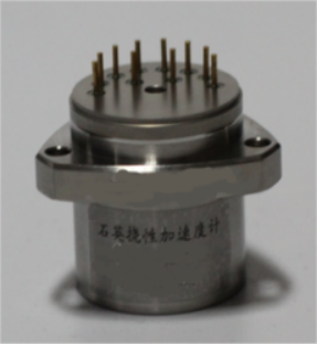
BDHD-EZK-IN-G50 Quartz Flexure Accelerometer
Product Specifications
The operating principle of a traditional quartz flexure accelerometer relies on an upper and lower torque coil assembly, a pendulum element, and a servo loop. In this design, the coils are bonded to the quartz flexure beams; together with the coil formers, they constitute the pendulum assembly to provide the proof mass for detecting external input acceleration.
The torque motor consists of a yoke, permanent magnets, pole pieces, and a compensation ring. The permanent magnets are made from suitable magnetic materials to generate the magnetic field. The yoke and pole pieces guide the magnetic flux through the yoke to form a closed magnetic circuit, while the compensation ring corrects for magnetic leakage. The upper and lower torque motors use an opposed-pole configuration to enable push-pull operation, and they are secured together with the flapper vane via a retaining band. When external acceleration is applied, inertial forces displace the flapper vane from its equilibrium position. This displacement changes the capacitance of the differential capacitor formed between the top and bottom surfaces of the vane and the end faces of the upper and lower torque motors. The resulting electrical signal is output through terminals to the servo loop. After amplification, the current is fed to the coils, where the Ampere force on the energized conductors within the magnetic field acts in a push-pull manner to restore the vane to its balanced position. At small deflection angles, this current is approximately linearly proportional to the input acceleration. By measuring this current, the magnitude of the input acceleration can be determined.
Pricing Details
Product price is negotiable and determined by order quantity, configuration requirements, and delivery terms.
Submit an inquiry using the form below. Our expert team will provide a detailed quote within 24 hours.
Product Details
The operating principle of a traditional quartz flexure accelerometer relies on upper and lower torque coils, a pendulum assembly, and a servo loop. The coils are bonded to the quartz pendulum beams; together with their bobbins, they form the pendulum assembly to provide the proof mass for detecting external acceleration inputs.
The torque motor consists of a yoke, permanent magnets, pole pieces, and a compensation ring. The permanent magnets are made from suitable magnetic materials to generate the magnetic field. The yoke and pole pieces guide the magnetic flux through the yoke to form a closed magnetic circuit, while the compensation ring corrects for magnetic leakage. The upper and lower torque motors use an opposed-pole configuration to enable push-pull operation, and they are secured together with the flapper vane via a retaining band. When external acceleration is applied, inertial forces displace the flapper vane from its equilibrium position. This displacement changes the capacitance of the differential capacitor formed between the top and bottom surfaces of the vane and the end faces of the upper and lower torque motors. The resulting electrical signal is output through terminals to the servo loop. After amplification, the current is fed to the coils, where the Ampere force on the energized conductors within the magnetic field acts in a push-pull manner to restore the vane to its balanced position. At small deflection angles, this current is approximately linearly proportional to the input acceleration. By measuring this current, the magnitude of the input acceleration can be determined.
Can't find the right product?
Contact our expert team for customized solutions tailored to your specific needs.
Contact Us